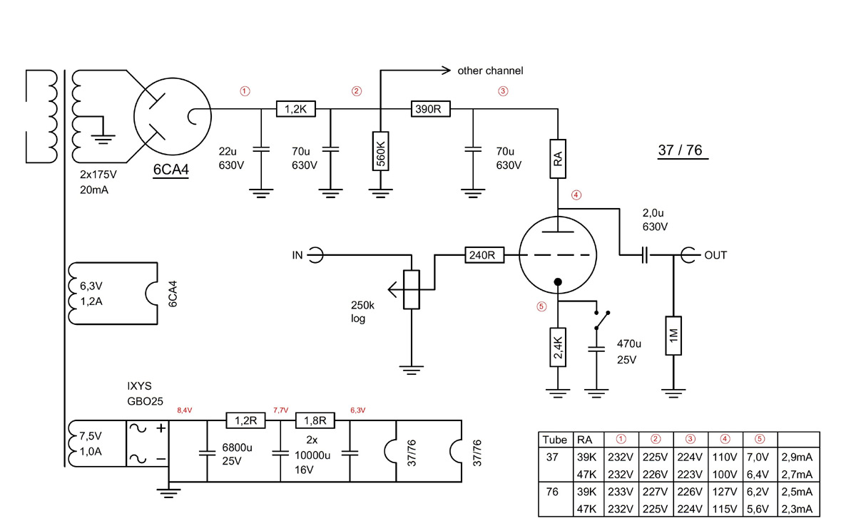
Tube Power Amp Schematic of Triode Preamplifier with 37 and 76 Pre Wartubes
The American prewar-types 37 and 76 have the same heater (6,3V / 0,3A) and quite similar plate-characteristics. So if you choose the design carefully you can simply change the tubes.


For example the loadlines are shown here:


The operating-point is chosen in a area with most parallel curves: Ug=-7,0V / Ia=3mA / Ua=100V. For the anode-resistor i took 2 values, 39k and 47k.
The slope of the loadline is determined by the load resistor and can be drawn with two points:
First Point: for example 300V on the x-axis
Second Point: the fictitious current when all the voltage drops across the resistor:
I = 300V / 39000R = 0,00769 = 7,7mA (point on the y-axis)
Just draw a straight line between those points and move it parallel so that it crosses the operating point.
Calculation of the value of the cathode resistors:
Operating point: Ug=-7V, Ia=3mA
Rk = 7V / 0,003A = 2333R = 2,4K
Calculating of the supply voltage:
Ug = 7V (between cathode and ground)
Ua = 100V (between cathode and anode)
Voltage drop across the anode-resistor: U = 39000R x 0,003A = 117V
Sum : 7 + 100 + 117 = 224 V
This value (without Ug) can also be read on the graph where the loadline crosses the x-axis.
Control calculation for the slope of the loadline:
220V / 0,0055mA = 40000 = approx. 39k
Even the values measured at the ready amp are matching:
back