Basic Triode Circuits
- Basic Recipes -(回路図三極 真空管 & 回路図 | 電路三極管 真空管 & 接线图)
The nice thing about triodes is how easy it is to build very simple circuits. That’s just the nature of the triode. Other interesting circuits (Cascode, SRPP, etc.) each have their own use and purpose. Here we only talk about the nostalgically simple line and power amplifier in single-ended class A circuits.
Cathode Base with Anode Resistance
The standard circuit is connected with a load-resistor RA and receives an automatic grid voltage generation by means of RK. In contrast to power amplifiers intended to achieve the greatest possible power output, for the pre-amplifiers you can select the resistance value RA more freely. Usually a lower resistance value is a better idea. That way, the output impedance of the circuit decreases, the transient response is improved and there are less distortions.
As a starting point for your experiments you can select an anode resistance of approximately 3 or 5 times the internal resistance of the tube at the operating point - or a ratio of approximately 0.6 for UA/B+.
You can find a very good tool for the theoretical testing of different operating points and load resistor-values here. Drawing a loadline in the graph of the Ua/Ia-curves of a tube is described for the 37/76-amp here.
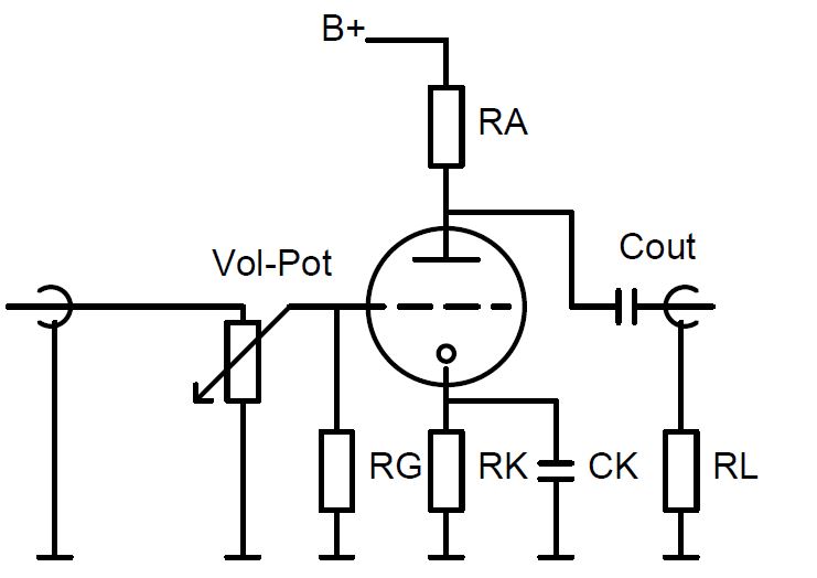 Grounded-cathode gain stage with anode-resitor
Cathode Base with Anode Choke
The ohmic resistance of RA can be replaced by an inductive load, an anode choke. A choke has a low DC resistance - so you can work with lower operating voltages. The transmission of low frequencies, however, will be difficult. The higher the internal resistance of the tube, the higher the inductance of the choke has to be. Anode chokes are therefore interesting for tubes with small internal resistances of up to approximately 5-8k.
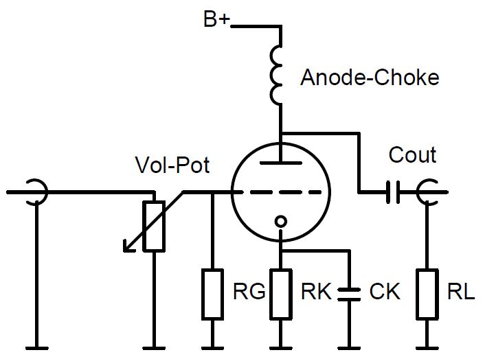 Grounded-cathode gain stage with anode-choke
Cathode Base with Line Output Transformer
The design of a triode pre-amplifier with a line transformer is the most consistent. The key advantage of this circuit is that you can eliminate the coupling capacitor at the output.
Just like with the anode choke, the internal resistance of the tube shouldn’t be too large. You can adjust the circuit according to the input resistance of the following power amplifier via the connected resistor RL. This has an influence mostly on the low-frequency sound.
You can get the transformers as interstage transformers with approximately the same input and output impedance (intended for the direct connection of a driver tube to an output tube "interstage transformer") or as a line output transformers with usually 600 ohm output impedance.
A real advantage of a transformer is the fact that a balanced output is available. Which is great, especially in connection with active studio monitors.
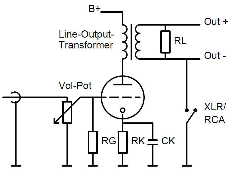 Grounded-cathode gain stage with Line-Out-Transformer