Designing and Building of a Triode Pre-Amplifier
- The Menu Plan -(真空管アンプ | 电子管放大器)
Tube Amplifier Components - Placement and Housing
It is often a long way from a nice and easy schematic to the final amplifier. You can start fiddling as soon as you know the dimensions of the biggest components (transformers, capacitators for the power supply, tubes, etc.).You should always adhere to the following guidelines:
- The distance between power supply and signal-carrying parts should be as large as possible. And the power supply includes, of course, mains leads and on-off switch. The most consistent way to achieve this is by choosing different housings for power supply and signal section.
- The distance between the AC wires (heating) and the signal-carrying wires should also be as large as possible. Straight cable harnesses look very orderly. AC voltage wires, however, should not be installed parallel to DC wires.
- If using big filter capacitors (electrolytic or oil paper capacitors), you can place them on top of the housing between power transformer/rectifier tube and signal tubes. This achieves a certain shielding. Direct heated pre-amp triodes react especially sensitive to various interferences. With a bit of luck you can then do without a special protective cover.
- The signal-carrying wires should be as short as possible. A big help in that regard are shaft extensions. They help you place the input selector and volume potentiometer near the input jacks.
But of course the pure doctrine demands as few solder points as possible...
Grounding
If you want a noise free and clean sound, a thorough grounding in the amplifier is essential.To achieve this, you have to be aware of two basic principles:
- You have to differentiate between the grounding of the housing, the power supply and the signal-section.
- In the ground wires currents are flowing.
In the power supply grounding of a multistage LC and RC filter the current flowing in the negative wires may show residual ripples. These are lower in the 3rd filter stage than in the 1st. But the high residual ripple of the 1st stage naturally must not overlap with the grounding of a later filter stage. This is why the 1st input-condenser is the point to connect the power supply grounding to the housing grounding. This also explains why power supply and signal grounding have to be separated. No one wants the residual ripple from the filter wires in the signal’s negative wire.
In the signal grounding the negative terminals of the different components of the circuit are connected, namely input and output jacks, volume potentiometers, grid resistor, cathode resistor/condenser and the last filter capacitator. You must connect the different signal groundings at the negative terminal of the last filter capacitator and then lead it to the housing.
You also have to watch out for ground loops for example in wire shields connected at both ends. The diagram shows the principle. This works brilliantly.
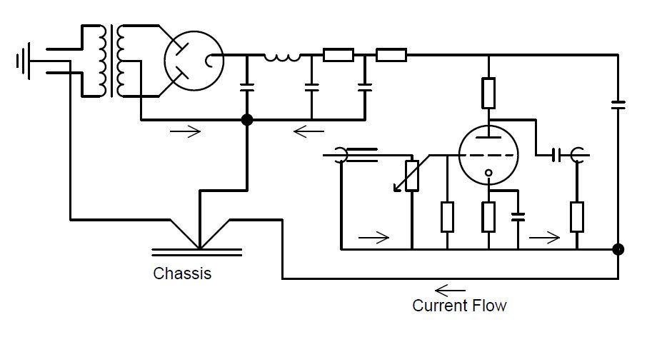 Schematic diagram of the grounding
Of course you can choose a different method as well, like the one shown in the pilot output stage from the 60s, as shown here. The old masters have simply used the entire housing as a grounding point, and I assume they knew exactly what they were doing.
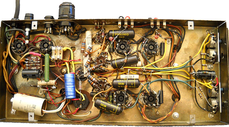
That way, everything also is a feast for the eyes :-)